Hardware
This page summarizes the physical hardware stack used to build Romi for ME 405, with emphasis on the components that directly enabled robust sensing, repeatable closed loop motion, and reliable autonomy during timed obstacle course runs. The system combines a differential drive base with embedded compute, power management, and multiple sensing modalities so that navigation decisions are always grounded in real time measurements rather than open loop assumptions.
Chassis and Drivetrain
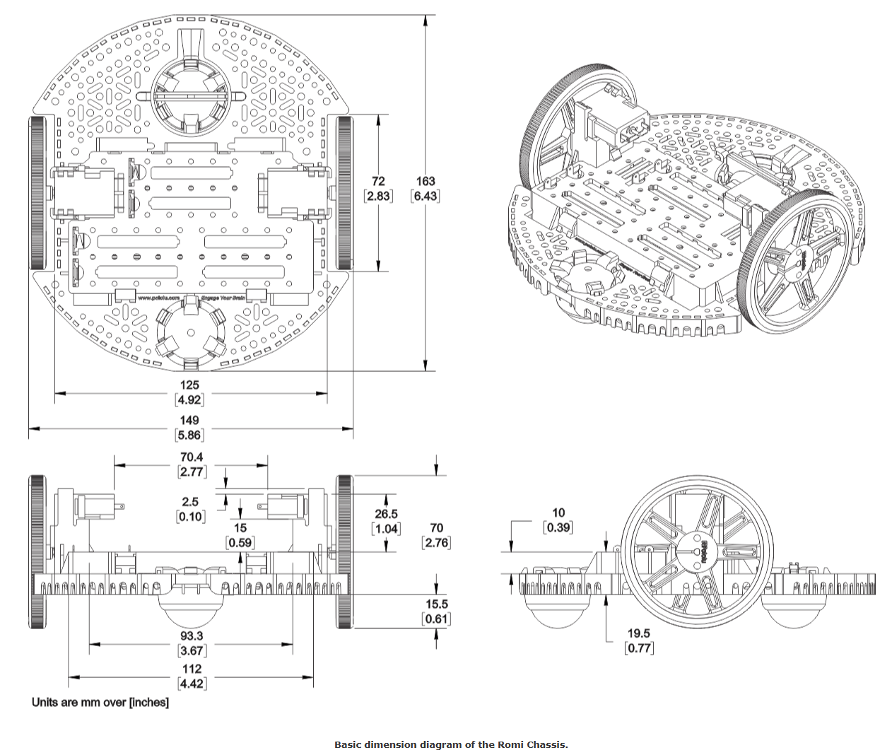
Romi uses a Pololu Romi differential drive chassis that integrates the mechanical structure, drive motors, wheels, and encoders with a compact power distribution scheme. This base provides a stable wheelbase for repeatable odometry and closed loop speed control while offering sufficient mounting real estate for sensor placement and cable routing.
Parameter |
Value |
Notes |
|---|---|---|
Wheel radius |
0.035 m |
Used for distance and velocity estimation from wheel motion |
Track width |
0.141 m |
Used for heading and turning kinematics |
Encoder resolution |
1437.1 ticks per rev |
Used to convert counts to wheel rotation and displacement |
Documentation provided by Polulu Robotics
Hardware |
Technical role in the system |
|---|---|
Romi chassis and power distribution |
Mechanical structure and regulated distribution to embedded electronics |
DC gearmotors |
Bidirectional actuation via PWM effort command |
Quadrature encoders |
High resolution wheel position feedback for speed, distance, and estimation |
Wheels |
Ground interface defining traction and kinematic scaling |
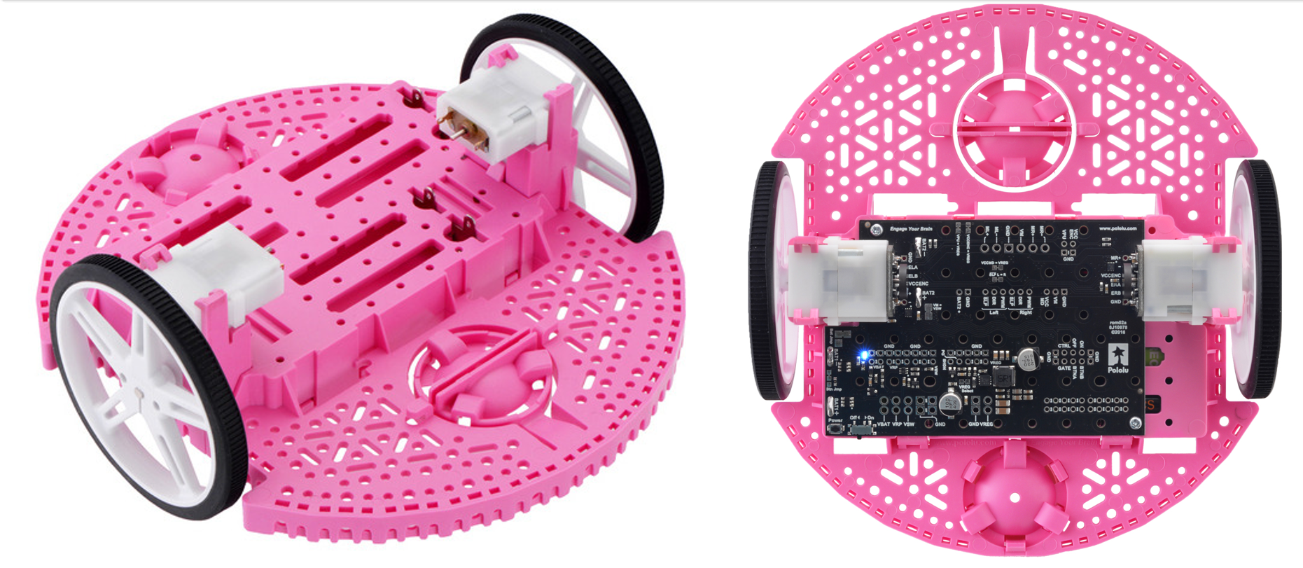
Romi chassis and drivetrain assembly used as the mechanical and power foundation for all sensing and control subsystems.
Power Distribution Board
The power distribution board serves as the electrical hub for Romi, routing battery power to the drivetrain and embedded electronics while providing a clean, repeatable connection point for system bring up and troubleshooting. It reduces wiring complexity by centralizing power and ground distribution, improves serviceability during repeated trials, and supports stable operation when motor loads introduce transients on the supply.
Item |
Technical role in the system |
|---|---|
Battery input and distribution |
Routes supply power to motors and controller wiring harnesses |
Ground reference distribution |
Provides a common return path for mixed digital and analog subsystems |
Modular connection points |
Simplifies integration, inspection, and rapid hardware iteration |
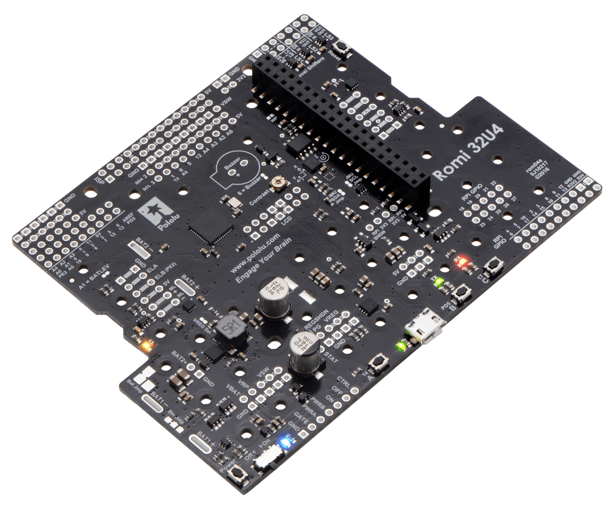
Power distribution board used to centralize battery power and ground routing for the drivetrain and embedded electronics.
Micro-controller Board
The embedded compute core is an STM32 Nucleo board used as the real time MicroPython target. It executes the cooperative task architecture, produces deterministic update timing for sensing and control loops, and exposes the timer, ADC, UART, and GPIO resources required to interface the full hardware stack.
Peripheral |
Application |
|---|---|
Timers and PWM |
Motor effort generation and time base for periodic tasks |
Encoder mode timers |
Quadrature position counting for each wheel |
ADC |
Battery monitoring through an external voltage divider |
UART / serial |
Telemetry, command interface, and debugging output |
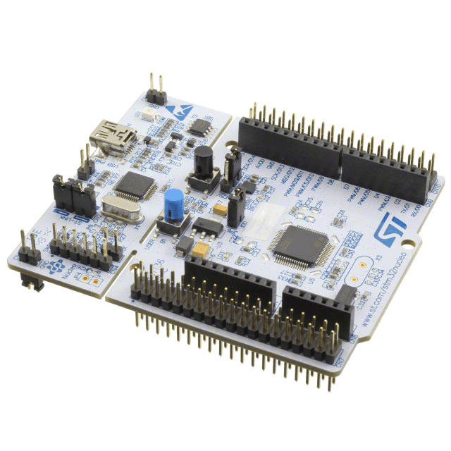
STM32 Nucleo controller providing real time I O, timers, and on board debugging for MicroPython firmware execution.
Shoe of Brian Interface Board
The Shoe of Brian board expands the Nucleo into a robust wiring interface by providing structured headers and routing for the project’s peripherals. This board simplifies integration by consolidating signal breakout, ground reference management, and connector level access so that sensors and actuators can be serviced and modified without rewiring the controller directly.
Feature |
Purpose |
|---|---|
Structured header breakout |
Clean signal routing to motors, sensors, and communication hardware |
Shared ground distribution |
Stable reference for mixed digital and analog measurements |
Rapid reconfiguration |
Supports iterative pin mapping and layout changes during bring up |
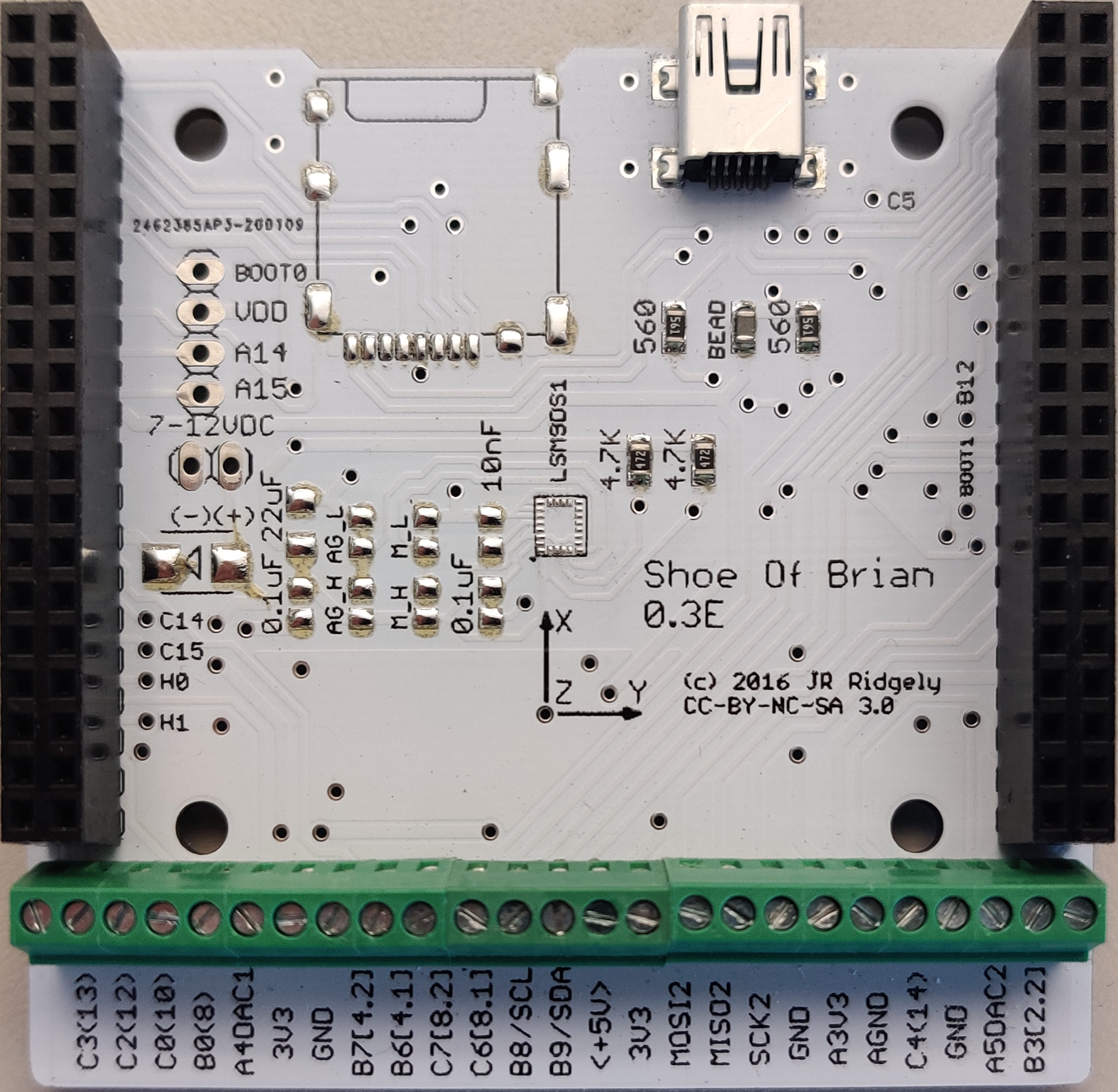
Shoe of Brian interface board used to organize wiring, route signals, and support rapid hardware iteration.
IMU
A BNO055 inertial measurement unit provides heading and yaw rate measurements used for turning control, heading stabilization, and state estimation. Communication is implemented over I2C, enabling low latency sensor polling and consistent integration with the task scheduler.
Item |
Value |
Notes |
|---|---|---|
Sensor |
BNO055 |
9 axis IMU with onboard fusion modes |
Bus |
I2C |
Software I2C implemented on microcontroller pins |
I2C address |
0x28 |
Default address used during initialization |
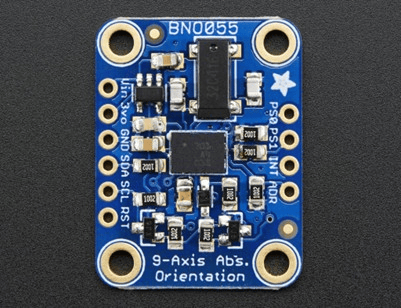
BNO055 IMU used to provide real time heading and yaw rate feedback for control and estimation.
Line Sensor
A Pololu QTR reflectance sensor array provides line detection and lateral error information for line following. The array’s physical mounting height and alignment are treated as controlled design parameters, supported by custom 3D printed mounts to maintain consistent reflectance geometry across runs.
Hardware |
Technical role in the system |
|---|---|
QTR reflectance array |
Measures surface reflectance profile for line detection and tracking error |
Custom mounting fixture |
Maintains repeatable sensor height and alignment relative to the floor |
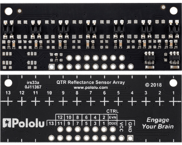
QTR reflectance sensor array mounted to maintain a controlled standoff distance for consistent line contrast and tracking performance.
Bump Sensor
A bumper switch assembly provides event detection for wall contact and collision handling. The configuration was simplified to present a single clean trigger condition to the navigation logic, enabling deterministic recovery behaviors without ambiguity in contact interpretation.
Hardware |
Technical role in the system |
|---|---|
Bump switch assembly |
Contact triggered event input for collision detection and recovery logic |
Single output wiring |
Reduces input complexity for a reliable digital trigger signal |
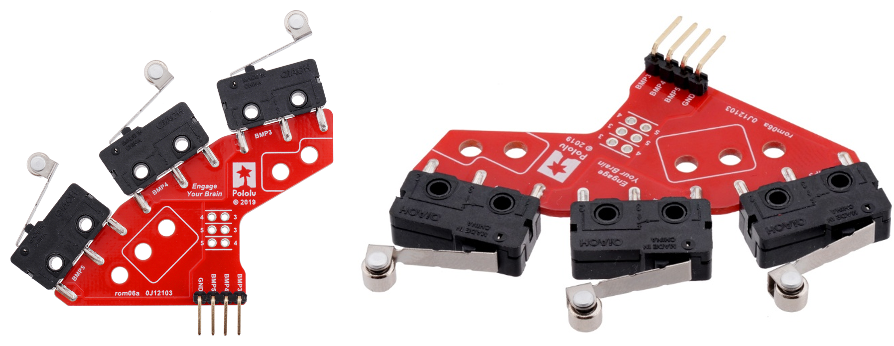
Bump sensor assembly providing a discrete event trigger used by navigation for contact response and recovery.