Tasks
This page documents the cooperative multitasking architecture used on Romi and the finite state machines that govern each subsystem task. The diagrams are intended to make the runtime behavior of the robot explicit by showing how sensing, estimation, control, and navigation execute concurrently under the cotask scheduler while exchanging information through task_share shares and queues. The task diagram describes system level signal flow, and the FSM diagrams describe how each task progresses through its internal operating modes during calibration, trial execution, navigation, and shutdown.
System Architecture Overview
Task Diagram
The task diagram represents the complete software architecture executed on the microcontroller during a run. Each box corresponds to a cooperative task implemented as a generator, and arrows represent the real time variables passed through task_share shares and queues. Low level tasks handle hardware interface and telemetry generation, mid level tasks implement control and estimation, and the top level navigation task coordinates the entire system by setting mode flags and setpoints rather than calling hardware directly. This separation is what allows Romi to run multiple subsystems simultaneously with deterministic timing while keeping the navigation logic readable and modular.
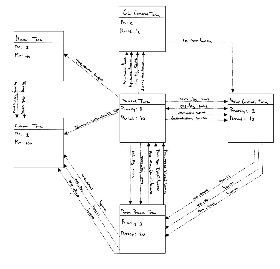
System task diagram showing the interconnection of all cooperative tasks and the data flow through shared variables and queues.
In operation, the serial task acts as the external command and calibration interface, the motor control tasks apply effort and produce encoder feedback, the closed loop control tasks compute effort commands for velocity tracking and line following, and the heading task converts encoder motion into distance and heading state estimates. Navigation consumes these estimates and sensor results to decide what behavior should be active at each point in the course. Event style tasks such as the bump sensor provide discrete triggers that allow navigation to enter recovery sequences, while sensing tasks such as the IMU handler provide inertial data used for heading stabilization and turn accuracy when enabled.
Individual Task State Machines
Serial Communication Task
The serial communication task represents the system’s external interface during calibration and timed trials. It listens for Bluetooth commands at high baud rate, parses parameter messages, and sets the shared variables that arm the run and configure control targets. This task also gates the IR calibration sequence by transitioning through explicit modes for black reference, white reference, and calibration completion, ensuring the line following controller receives normalized sensor data before the robot begins autonomous motion.
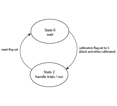
Serial task FSM managing Bluetooth command parsing, calibration sequencing, and trial start and stop control.
In its waiting mode, the task continuously checks for ASCII commands and updates shared variables such as desired velocity, trial time, and calibration flags. After parameters and calibration are complete, it asserts start flags that enable the drivetrain tasks and control tasks to begin execution. During an active trial, the task monitors for stop commands and end conditions, then drives a clean termination by asserting end flags and clearing any buffered logging queues so the next run begins from a consistent state.
Motor Control Task
The motor control task represents the lowest level actuation and wheel telemetry subsystem. Two identical instances run simultaneously, one for the left drivetrain and one for the right drivetrain. Each task is responsible for enabling the motor driver, applying the commanded PWM effort setpoint, updating encoder position and velocity at high rate, and publishing telemetry through shared variables so that closed loop control and estimation remain synchronized with the drivetrain.
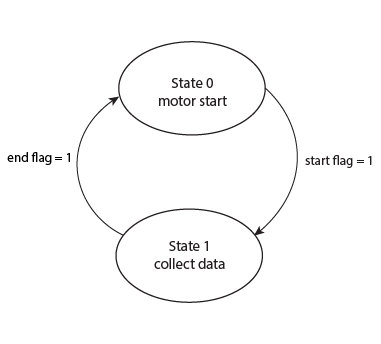
Motor control FSM enabling the driver, zeroing the encoder, applying PWM effort, and publishing encoder telemetry during a trial.
The start state holds the motor disabled until a shared start flag is asserted, then enables the driver and zeroes the encoder to establish a consistent reference. During the data collection state, the task repeatedly calls the encoder update routine, computes a filtered velocity estimate, updates shared values for position, speed, and elapsed time, and applies the latest effort command using the motor driver interface. The task monitors time limits and end flags to disable the motor cleanly and return to the start state for the next trial.
Closed-Loop Control Task
The closed loop control task represents the velocity, line tracking, and turning control layer that generates drivetrain effort commands. Two instances run simultaneously, producing independent effort outputs for the left and right motor control tasks. The controller supports multiple operating modes so that navigation can switch between line following segments, forced straight segments, and heading based turns while preserving stable PI velocity regulation underneath.
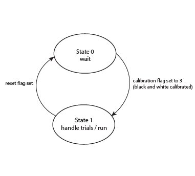
Closed loop control FSM implementing PI velocity regulation with line following correction, rest mode, and heading based turning mode.
In its main run state, the controller tracks a desired velocity using encoder speed feedback with PI regulation and saturation handling. When line following is enabled, it adds a reflectance based centroid error term that biases left and right effort commands in opposite directions to steer back to the tape, and it manages integral accumulation to prevent windup during saturation. When force straight mode is enabled, line correction is suppressed and the controller prioritizes heading stability. In the turn state, the controller interprets a target heading from navigation, wraps heading error into a bounded range, and applies a dedicated PI turn law to drive the robot into the desired angular window before returning to the run state.
Encoder Heading Task
The encoder heading task represents the real time odometry estimator based on differential drive kinematics. It runs as a continuous periodic loop rather than a multi state FSM, converting left and right encoder motion into forward distance traveled and heading change. This task provides the primary state variables used by navigation to trigger distance based transitions and to evaluate heading error during forced straight and turn segments.
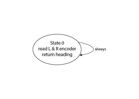
Encoder heading task FSM showing continuous periodic odometry computation with unwrapping and normalization.
Each update converts encoder ticks into wheel displacement, integrates the average displacement into distance, and integrates the wheel displacement difference into heading using the known track width. To keep the heading estimate usable for control, the algorithm handles wraparound at plus or minus 180 degrees by unwrapping discontinuities and re normalizing the final heading into a consistent range. The output shares provide a continuously updated distance and heading estimate that all higher level logic can consume without directly reading encoder hardware.
Bump Sensor Task
The bump sensor task represents a discrete event detector used for wall interaction handling. It continuously monitors a digital input and sets a shared bump flag when contact is detected, providing a clean trigger for navigation to transition into a recovery routine. The task is designed to avoid noisy repeated triggers by enforcing a single confirmed event per run using debounce logic and a latched detected state.
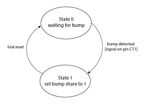
Bump sensor task debouncing contact input and publishing a single collision event flag to navigation.
Because this task publishes an event rather than a continuous measurement, its output is treated as an interrupt style condition within the FSM logic. When asserted, navigation can reliably assume a collision occurred and execute a deterministic recovery sequence without ambiguity due to switch chatter or vibration.