Wiring
This page defines the electrical interconnects used on Romi, including motor driver control, encoder feedback, reflectance sensing, inertial sensing, bump event inputs, battery monitoring, and Bluetooth serial communication. The goal is to provide a single reference for connector level wiring, Nucleo pin assignments, and the signals required by each subsystem task.
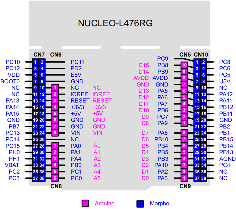
STM32 Nucleo pinout reference used to assign timer, ADC, I2C, and UART signals for the Romi wiring harness.
Nucleo Pin Constraints
Several STM32 Nucleo pins are reserved for onboard functions such as ST-Link communication, USB, SWD programming, the user LED and button, and the 32 kHz oscillator. These pins were treated as unavailable during integration to preserve reliable REPL access, firmware flashing, and debugging support throughout development and testing.
Reserved Nucleo pins that were avoided to prevent conflicts with ST-Link, USB, SWD, onboard LED and button, and RTC oscillator functions.
Reserved pins not used in this project
Nucleo Pin |
Arduino Label |
Reserved Function |
|---|---|---|
PA2 |
A2 |
UART2 link to ST-Link interface |
PA3 |
A3 |
UART2 link to ST-Link interface |
PA5 |
A5 |
Onboard user LED |
PA11 |
A11 |
USB interface signals through the shoe |
PA12 |
A12 |
USB interface signals through the shoe |
PA13 |
A13 |
SWD programming interface |
PA14 |
A14 |
SWD programming interface |
PC13 |
C13 |
User button input |
PC14 |
C14 |
32 kHz oscillator for RTC |
PC15 |
C15 |
32 kHz oscillator for RTC |
Motor Control
Motor driver pin mapping
| Motor | Signal | NUCLEO Pin | Timer / Channel |
|---|---|---|---|
| Left | Enable | PB0 | Digital output |
| Left | PWM A | PC12 | TIM3 CH3 |
| Left | PWM B | PC10 | TIM3 CH3 |
| Right | Enable | PC9 | Digital output |
| Right | PWM A | PH1 | TIM3 CH4 |
| Right | PWM B | PH0 | TIM3 CH4 |
Motor control wiring using TIM3 PWM channels for effort commands and dedicated enable lines for each motor driver.
Encoder Connections
Quadrature encoder mapping
| Encoder | Signal | NUCLEO Pin | Timer / Channel |
|---|---|---|---|
| Left | Channel A | PA0 | TIM2 CH1 |
| Left | Channel B | PB3 | TIM2 CH2 |
| Right | Channel A | PA8 | TIM1 CH1 |
| Right | Channel B | PA9 | TIM1 CH2 |
Encoder wiring using hardware timer encoder mode to produce wheel position and velocity feedback for control, odometry, and navigation.
Battery Monitoring
Battery ADC input
| Signal | NUCLEO Pin | Notes |
|---|---|---|
| Battery ADC | PC0 | ADC input from voltage divider output |
Battery voltage measurement routed to an ADC channel for runtime monitoring and diagnostics.
IR Sensor Array
Reflectance sensor channel mapping
| Channel | NUCLEO Pin | Position |
|---|---|---|
| 1 | PC4 | Left far |
| 2 | PB1 | Left mid |
| 3 | PA7 | Left near |
| 4 | PC1 | Center |
| 5 | PA4 | Right near |
| 6 | PA1 | Right mid |
| 7 | PC3 | Right far |
Seven channel reflectance array wiring used for centroid based line error computation in the line following controller.
IMU Connections
BNO055 I2C and reset mapping
| BNO055 Pin | Wire Color | NUCLEO Pin | Notes |
|---|---|---|---|
| SDA | Purple | B14 | I2C data |
| SCL | Grey | B13 | I2C clock |
| RST | White | B15 | Hardware reset line |
BNO055 wiring over I2C with a dedicated reset pin to support deterministic startup and calibration handling.
Bump Sensors
Bump sensor wiring and jumpers
| Side | Board Pin | Wire Color | NUCLEO Pin |
|---|---|---|---|
| Right | BMP 0 | Purple | C11 |
| Right | BMP 1 | - | Jumper to 0 |
| Right | BMP 2 | - | Jumper to 0 |
| Left | BMP 3 | Teal | Jumper to 2 |
| Left | BMP 4 | - | Jumper to 3 |
| Left | BMP 5 | - | Jumper to 3 |
Bump sensor wiring consolidated into a single event input used by navigation for collision detection and recovery sequencing.
Bluetooth Serial
UART1 Bluetooth pin mapping
| Signal | NUCLEO Pin | Notes |
|---|---|---|
| TX | B6 | UART1 transmit to Bluetooth RX |
| RX | B7 | UART1 receive from Bluetooth TX |
Bluetooth serial link on UART1 used for calibration commands, trial parameters, and runtime telemetry at 460800 baud.
Full Assembly
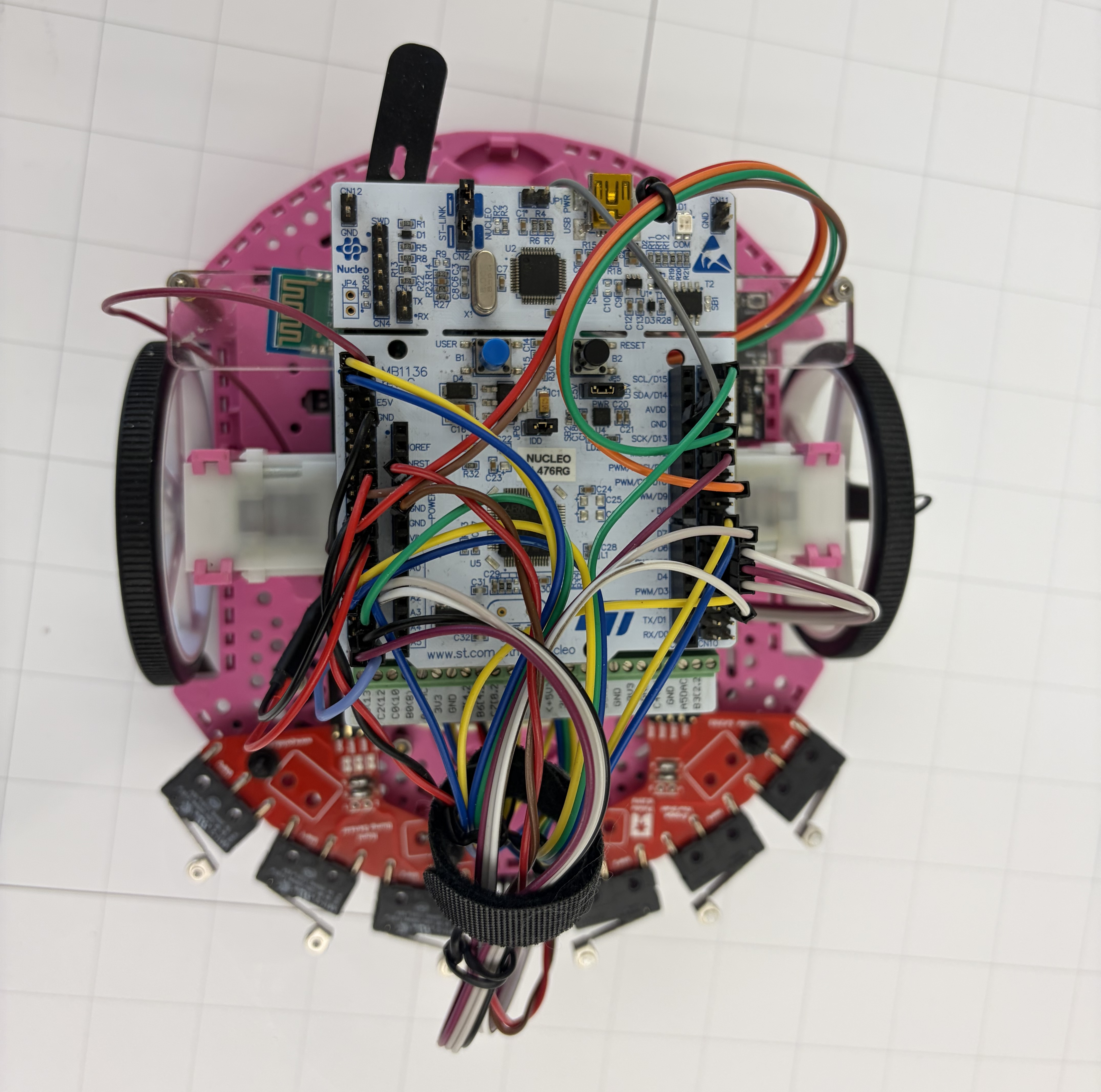
Fully assembled Romi with integrated wiring harness, controller stack, and sensor mounts configured for obstacle course trials.